
Stainless Steel Vacuum Bottle Tooling & Mold Development Guide: Mold Types, Lifespan, Costs & OEM Drawing Standards
I. Introduction: Tooling — The Engineering Bridge from Concept to Mass Production
In the custom OEM/ODM development of stainless steel vacuum bottles, tooling and mold development is the single most critical phase that determines whether a product design can be successfully manufactured, maintain consistent quality, and achieve cost-efficiency.
Many overseas clients create stunning 3D renderings and industrial design CADs for drinkware, but often lack systematic knowledge about the industrial details of mold making: What specific molds are required for a vacuum bottle? How long does a mold last? How are tooling costs calculated? How long does it take from drawings to T1 samples? What CAD file formats should clients provide?
As a technical director at an OEM/ODM factory with over a decade of experience in premium vacuum insulated container manufacturing, this white paper provides a comprehensive, systematic guide to stainless steel vacuum bottle tooling.
II. Classification of Drinkware Molds (Metal, Plastic, Silicone & Fixtures)
A complete stainless steel vacuum bottle consists of a stainless steel body (inner liner, outer shell, bottom cap), plastic components (lid casing, threaded plug, spout, flip lock, handle, tea strainer), and silicone seals (gaskets, O-rings, stopper valves). Therefore, drinkware tooling is never just "one single mold," but a cluster of specialized tooling across metal, plastic, and silicone domains:
1. Stainless Steel Body Forming Tooling & Jigs
Manufacturing a stainless steel bottle body involves metal plastic deformation and secondary machining, utilizing four primary types of tooling:
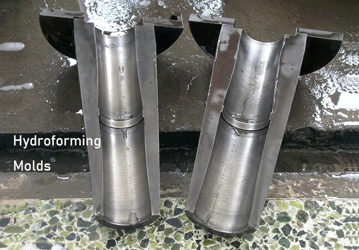
Hydroforming Dies (Hydroforming Molds):
- Principle & Function: A circular 304 or 316 stainless steel tube is placed inside a two-piece split die cavity. High-pressure water (hundreds of megapascals) is injected into the tube, uniformly expanding it against the mold walls to form contoured, waisted, or curved bottle profiles.
- Characteristics: High production efficiency, uniform radial wall stretch, minimal material stress concentration.
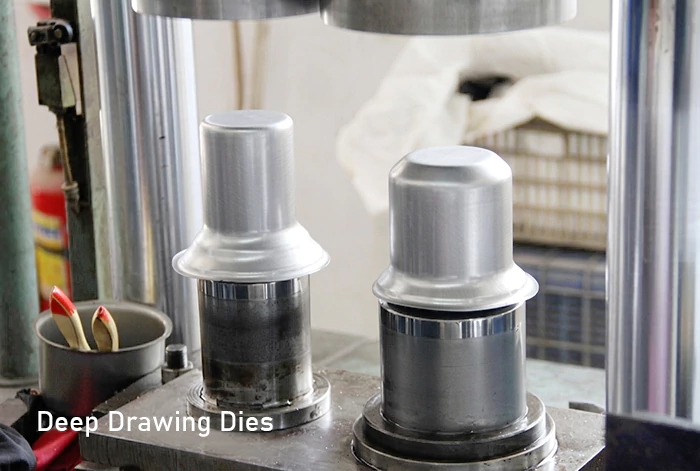
Deep Drawing Dies:
- Principle & Function: For non-cylindrical bottles (e.g., square or flat bottles), squat food jar liners, or stainless steel lid cores that cannot be hydroformed from round tubes, sheet metal must be progressively drawn through multi-stage stamping dies.
- Components: Blanking die, 1st–5th stage drawing dies, sizing/calibrating die, and trimming die.
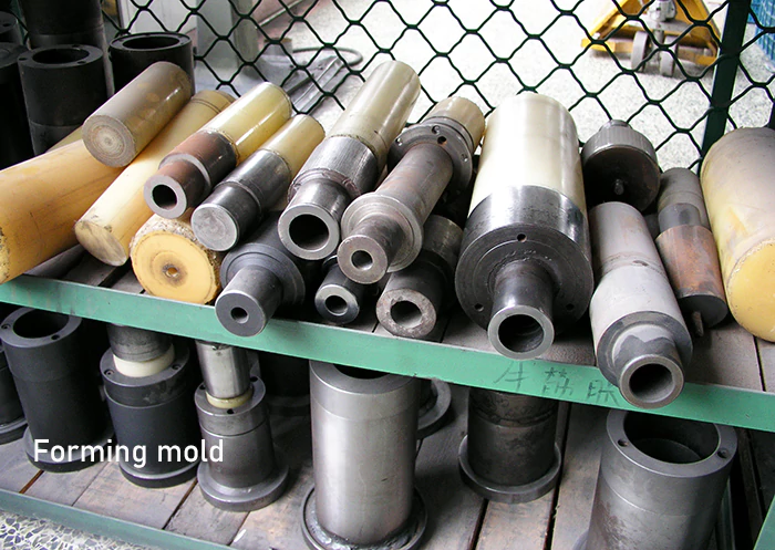
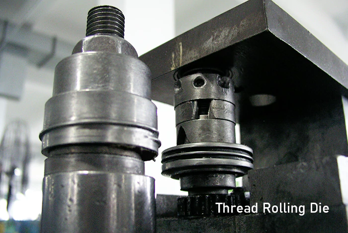
Secondary Machining & Forming Tooling:
- Necking Die: Reduces the upper diameter of the expanded tube body to create the bottleneck.
- Thread Rolling Die: Presses precision threads onto the bottle neck or mouth.
- Facing & Bottom Flattening Tools: Trims excess tube rim burrs and flattens/flanges the bottom edge.
- Bottom Cap Stamping Die: Stamps the stainless steel outer protective bottom cap or vacuum sealing bottom disc.
Jigs, Fixtures & Inspection Gauges:
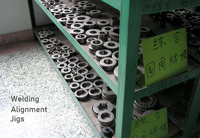
- Welding Alignment Jigs: Precision rotary positioning fixtures for inner/outer liner assembly and laser/TIG welding at the mouth and bottom.
- Surface Treatment Fixtures: Custom polishing machine clamps, electrostatic powder coating hanging rigs, and 360° laser engraving rotary fixtures.
- Quality Inspection Gauges: Vacuum testing manifolds, pneumatic leakage water-bath fixtures, and Go/No-Go thread gauges.
2. Plastic Injection Molds
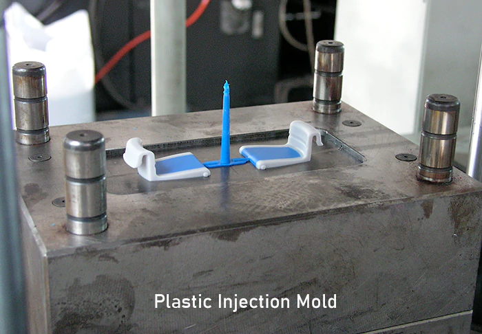
- Applicable Components: Outer cap shell, threaded inner plug, drinking spout, flip lock button, carrying handle, tea strainer, etc.
- Common Materials: Food-grade PP (Polypropylene), Tritan (Copolyester), ABS, POM (for high-strength latches).
- Key Tooling Challenges:
- Thread Unscrewing Mechanism: Drinkware caps feature internal precision threads, requiring hydraulic cylinder unscrewing mechanisms or collapsible cores to prevent thread damage during ejection.
- Sealing Groove Tolerance: Sealing ring grooves must maintain tight flatness and depth tolerances within $\pm0.03\text$ to prevent fluid leakage.
3. Silicone Molds (Compression & Injection Molds)
- Applicable Components: Leak-proof Gaskets/O-rings, stopper plugs, silicone straws, anti-slip boots, heat-resistant sleeves.
- Common Materials: Food-grade Solid Silicone or Liquid Silicone Rubber (LSR).
- Mold Types:
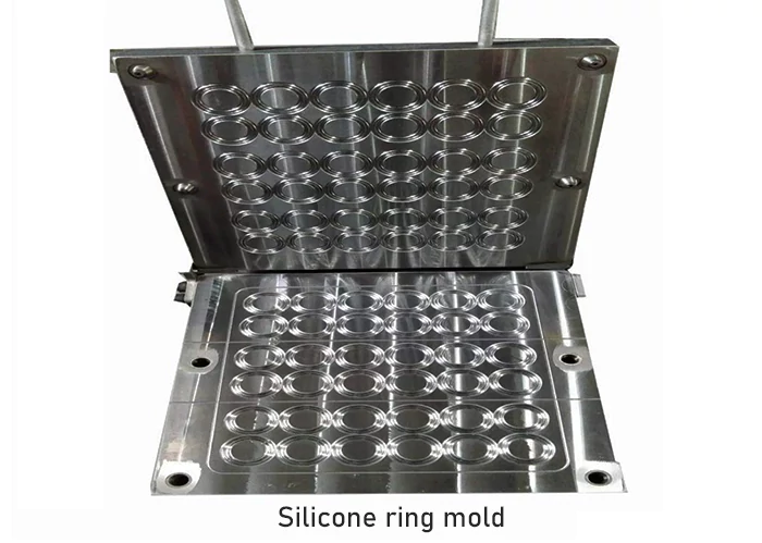
- Solid Silicone Compression Molds: Lower tooling cost, ideal for standard O-rings and simple boots.
- Liquid Silicone Rubber (LSR) Injection Molds: Extremely high precision, flash-free automated ejection, medical-grade hygiene, ideal for complex spouts and dynamic seal valves.
III. Mold Lifespan, Tooling Costs, Lead Times & Recommended MOQs
| Tooling Category | Typical Lifespan (Cycles) | Est. Tooling Cost (USD) | Lead Time (Days) |
| Partial (Hydroforming only) | 100,000 – 300,000 | $3,000 – $6,000 | 25 – 35 |
| Standard Full OEM | 300,000 – 500,000 | $12,000 – $30,000 | 45 – 55 |
| Complex / Custom Lid | 500,000+ | $30,000 – $50,000+ | 50 – 60 |
1. Mold Lifespan (Number of Shots / Cycles)
Mold longevity depends on tool steel selection (e.g., Cr12MoV, D2, SKD11, S136, 718H) and heat treatment (vacuum quenching, chrome plating, nitriding):
- Stainless Steel Hydroforming / Stamping Dies: Typically 100,000 to 300,000 cycles. High metal stamping friction causes wear, but replacing die inserts or re-polishing can extend service life.
- Plastic Injection Molds: Made of hardened corrosion-resistant steel (S136 or 718H), lasting 300,000 to 500,000 shots (up to 1,000,000 shots for premium steel).
- Silicone Molds: Typically 100,000 to 200,000 cycles.
2. Recommended MOQ & Tooling Cost Refund Policy
- Why is there an MOQ for new tooling projects? Setting up automated hydroforming, laser welding, powder coating, and injection machinery incurs significant setup scrap and pre-heating losses.
- Recommended MOQ: Initial production run MOQ for custom tooling projects is typically 10,000 – 20,000 PCS per mold.
- Tooling Cost Refund Policy: Honogo offers a cumulative volume tooling refund model. When cumulative purchase volume reaches agreed milestones (e.g., 100,000 – 200,000 PCS), 100% of the tooling fee is credited back to the client in subsequent orders.
IV. The Complete 8-Step Tooling & Development Workflow
To ensure zero-defect development, Honogo enforces a strict 8-step tooling control workflow:
- Requirement Analysis & Feasibility Study: Evaluate capacity, thermal performance specs, leak-proof rating, and target unit cost.
- DFM Engineering & Structural Optimization: Optimize draft angles, wall thickness uniformity, hydroforming stretch ratios, and thread engagement clearances.
- 3D Prototyping & Physical Verification (SLA & CNC): Produce 1:1 functional prototypes via SLA 3D printing and CNC machining to test ergonomic grip and thread smoothness before cutting steel.
- 3D/2D Mold Design & Review Sign-Off: Perform Moldflow Analysis, determine parting lines, gate locations, and ejection pins.
- Precision Mold Machining & Assembly: Execute CNC milling, wire EDM, heat quenching, nitriding, and mirror polishing.
- Trial Run & T0/T1 Sample Testing: Produce T1 samples for thermal retention tests, 24-hour inverted leak tests, and drop tests.
- Tooling Fine-Tuning & Pilot Production: Adjust tolerances based on T1 feedback, approve the "Golden Sample," and run a 500–1,000 unit pilot trial.
- Mass Production & Ongoing Tooling Maintenance: Transfer tooling to automated lines. Factory manages routine anti-rust treatments and preventive maintenance.
V. Required CAD & Drawing File Formats for OEM Development
To streamline technical evaluation and eliminate engineering misinterpretation, clients should provide standardized drawing file formats:
1. 3D CAD File Formats (Essential)
- Preferred Universal Lossless Solid Formats:
- .STEP (.stp) — Strongly Recommended. Cross-platform neutral solid model containing full geometric and topological data.
- .IGES (.igs) — Universal surface model format.
- Native CAD Formats:
- .SLDPRT / .SLDASM (SolidWorks)
- .PRT (PTC Creo / Siemens UG NX)
- ⚠️ Formats Unsuitable for Tooling: Polygon/mesh formats such as .STL, .OBJ, or .3DS. These lack parametric geometry for CNC programming and must be completely remodeled.
2. 2D Engineering Drawings (Tolerances & Critical Specs)
3D models cannot convey fit tolerances or surface finishes. They must be accompanied by 2D engineering drawings in .DWG, .DXF, or high-resolution .PDF.
- Essential Specifications:
- Critical Fit Tolerances: Mouth sealing grooves and thread engagement (typically requiring $\pm0.05\text$).
- Material Specifications:g., Inner liner: SUS316; Outer shell: SUS304; Lid: Food-grade PP / Tritan.
- Wall Thickness & Net Weight Targets.
- CMF & Surface Finishing: Pantone color codes, finish type (Powder Coating, Spray Painting), and Logo dimensions.
VI. Conclusion & Technical Support from Hono
Tooling is the foundation of stainless steel vacuum bottle manufacturing. Well-engineered, precision-machined tooling drastically reduces mass-production defect rates and delivers seamless, high-end product experiences for your brand.
As a specialized OEM/ODM manufacturer with over a decade of experience, Hangzhou Herong / Hono Housewares Co., Ltd. (Honogo) operates dedicated mold R&D and CNC machining workshops. Our engineering team provides end-to-end technical support from Concept Evaluation to Global Mass Production.
If you are planning to develop a custom vacuum bottle, outdoor tumbler, or food jar, contact Honogo's engineering team today!
- Official Website: https://honogo.com
- Business & Engineering Inquiries: Duncan Chen | info@honogo.com
- Core Expertise: Stainless Steel Insulated Water bottle Bottles, Non-Cylindrical Thermal Flasks, Plastic & Silicone Tooling, OEM/ODM Engineering Services